Dr. Andrew C. Pineda, Albuquerque High Performance Computing Center
Dr. Shashi P. Karna, Air Force Research Laboratory

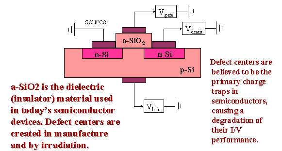
Shown in the demos are cluster models that we believe represents the local structure of what is called an E' (E prime) defect in amorphous silicon dioxide (a-SiO2). Amorphous silicon dioxide is the dielectric material (insulator) used in making today's semiconductor devices. These defects are the primary charge trap centers in these devices and are created during manufacture and by exposure to high-energy radiation. Charge trapping plays a major role in degrading the performance and causing failures in current semiconductors, and is of greater significance as the size of these devices are reduced. In order to control defect formation, an understanding of their local structure is needed. Cluster models studied using ab initio quantum mechanical methods allow us to understand the structure and properties of these defects.
Most of what we know about the structure these defects comes from an analysis of measurements of ESR (electron spin resonance) spectra. ESR is sometimes called EPR for electron paramagnetic resonance, and measures the splitting of energy levels of unpaired electrons when placed in a magnetic field. The unpaired electrons essentially behave as small magnets whose orientation can be flipped by a microwave signal. The frequency at which the orientation can be flipped is determined by the strength of the applied magnetic field.
Among the E' defects, two are believed to have a structure like that shown in the movies. The positively charged E'
g (E' gamma) defect is believed to look like the starting configuration in movie clip A, in which one of the central silicon atoms has moved away from a vacancy site were a single oxygen atom has been removed. The likewise positively charged E'd (E' delta) defect is believed to have the two silicon atoms adjoining each other near the vacancy site as in the starting configuration in movie clip B.A model proposed by Feigl, Fowler, and Yip (FFY) for the formation mechanism of related defects in
a-quartz (alpha-quartz) has been widely used to describe the formation mechanism of the positively charged E'g defect in a-SiO2. According to the FFY model, when a two silicon vacancy center like that shown in the movie traps a positive charge, one of the silicon atoms (black in the movie) spontaneously moves away from the vacancy and binds to an oxygen atom (red in the movie) in the adjoining SiO2 network, taking with it the positive charge. An unpaired electron is left on the remaining silicon atom which gives rise to a huge splitting the ESR spectrum of 420 Gauss. (Gauss is a unit of magnetic field strength.) Our studies of the related E'd defect shows that when a 2 silicon vacancy center traps a positive charge that the 2 silicons can remain in the vacancy sharing the unpaired electron giving rise to an approximately 100 Gauss splitting in the ESR spectrum. Both types of defects have been observed. So how do we explain their formation in light of the FFY model?We believe that the size and flexibility of the ring structures in a-SiO2 play a key role in determining which type of defect is formed. Movie clip A shows a cluster with small, relatively inflexible cluster, starting in a distorted configuration reminiscent of E'
g. An energy minimization optimization using the GAMESS electronic structure code shows that this configuration is very unstable with respect to the E'd -like configuration. Movie clip B shows a cluster with a large, flexible ring system initially in a symmetric configuration with both Si atoms in the vacancy (a la E'd). An energy minimization optimization shows that this system favors asymmetric distortion into an E'g-like configuration. For the quantum chemistry cognosenti out there, the small model was analyzed using a DZV basis set with polarization, and the large model was analyzed with the simpler "minimal" basis set, STO-3G.Note that the tubes are shown in the movies only to give a rough idea of the connectivity in the cluster. They do not necessarily indicate what the bonding looks like in the cluster at each step of the optimization.
The animations were generated using IBM Data Explorer to generate the frames, and Ulead GIF animator (Windows software) to create the movies.